- 您现在的位置:买卖IC网 > Sheet目录3887 > PIC16F84A-04E/SS (Microchip Technology)IC MCU CMOS 4MHZ 1K FLASH 20SSOP
PIC16F84A
DS35007B-page 28
2001 Microchip Technology Inc.
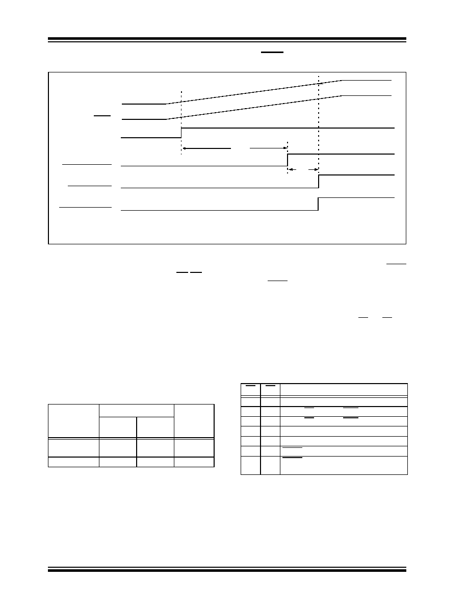
FIGURE 6-9:
TIME-OUT SEQUENCE ON POWER-UP (MCLR TIED TO VDD):
SLOW VDD RISE TIME
6.7
Time-out Sequence and
Power-down Status Bits (TO/PD)
sequence is as follows:
1.
PWRT time-out is invoked after a POR has
expired.
2.
Then, the OST is activated.
The total time-out will vary based on oscillator configu-
ration and PWRTE configuration bit status. For exam-
ple, in RC mode with the PWRT disabled, there will be
no time-out at all.
TABLE 6-5:
TIME-OUT IN VARIOUS
SITUATIONS
Since the time-outs occur from the POR pulse, if MCLR
is kept low long enough, the time-outs will expire. Then
bringing MCLR high, execution will begin immediately
(Figure 6-6). This is useful for testing purposes or to
synchronize more than one PIC16F84A device when
operating in parallel.
Table 6-6 shows the significance of the TO and PD bits.
Table 6-3 lists the RESET conditions for some special
registers, while Table 6-4 lists the RESET conditions
for all the registers.
TABLE 6-6:
STATUS BITS AND THEIR
SIGNIFICANCE
VDD
MCLR
V1
When VDD rises very slowly, it is possible that the TPWRT time-out and TOST time-out will expire before VDD
has reached its final value. In this example, the chip will reset properly if, and only if, V1
≥ VDD min.
INTERNAL POR
TPWRT
TOST
PWRT TIME-OUT
OST TIME-OUT
INTERNAL RESET
Oscillator
Configuration
Power-up
Wake-up
from
SLEEP
PWRT
Enabled
PWRT
Disabled
XT, HS, LP
72 ms +
1024TOSC
RC
72 ms
——
TO
PD
Condition
11
Power-on Reset
0x
Illegal, TO is set on POR
x0
Illegal, PD is set on POR
01
WDT Reset (during normal operation)
00
WDT Wake-up
11
MCLR during normal operation
10
MCLR during SLEEP or interrupt
wake-up from SLEEP
发布紧急采购,3分钟左右您将得到回复。
相关PDF资料
PIC16F84A-04E/SO
IC MCU CMOS 4MHZ 1K FLASH 18SOIC
PIC16F785-I/SS
IC PIC MCU FLASH 2KX14 20SSOP
PIC16C433T-I/SO
IC MCU CMOS 8BIT 10MHZ 2K 18SOIC
PIC16C773T-E/SO
IC MCU OTP 4KX14 A/D PWM 28SOIC
PIC16CE623T-30/SO
IC MCU OTP 512X14 EE COMP 18SOIC
PIC16F1825-E/ML
MCU PIC 14K FLASH 1K RAM 16QFN
PIC16F1828-I/SO
IC PIC MCU 8BIT 14KB FLSH 20SOIC
PIC16F688-I/SL
IC PIC MCU FLASH 4KX14 14SOIC
相关代理商/技术参数
PIC16F84A-04I/P
功能描述:8位微控制器 -MCU 1.75KB 68 RAM 13 I/O 4MHz Ind Temp PDIP18 RoHS:否 制造商:Silicon Labs 核心:8051 处理器系列:C8051F39x 数据总线宽度:8 bit 最大时钟频率:50 MHz 程序存储器大小:16 KB 数据 RAM 大小:1 KB 片上 ADC:Yes 工作电源电压:1.8 V to 3.6 V 工作温度范围:- 40 C to + 105 C 封装 / 箱体:QFN-20 安装风格:SMD/SMT
PIC16F84A-04I/P
制造商:Microchip Technology Inc 功能描述:IC 8BIT FLASH MCU 16F84 DIP18
PIC16F84A-04I/SO
功能描述:8位微控制器 -MCU 1.75KB 68 RAM 13 I/O 4MHz Ind Temp SOIC18 RoHS:否 制造商:Silicon Labs 核心:8051 处理器系列:C8051F39x 数据总线宽度:8 bit 最大时钟频率:50 MHz 程序存储器大小:16 KB 数据 RAM 大小:1 KB 片上 ADC:Yes 工作电源电压:1.8 V to 3.6 V 工作温度范围:- 40 C to + 105 C 封装 / 箱体:QFN-20 安装风格:SMD/SMT
PIC16F84A-04I/SO
制造商:Microchip Technology Inc 功能描述:8BIT FLASH MCU SMD 16F84 SOIC18
PIC16F84A-04I/SS
功能描述:8位微控制器 -MCU 1.75KB 68 RAM 13 I/O 4MHz IndTemp SSOP20 RoHS:否 制造商:Silicon Labs 核心:8051 处理器系列:C8051F39x 数据总线宽度:8 bit 最大时钟频率:50 MHz 程序存储器大小:16 KB 数据 RAM 大小:1 KB 片上 ADC:Yes 工作电源电压:1.8 V to 3.6 V 工作温度范围:- 40 C to + 105 C 封装 / 箱体:QFN-20 安装风格:SMD/SMT
PIC16F84A-04I/SS
制造商:Microchip Technology Inc 功能描述:8BIT FLASH MCU SMD 16F84 SSOP20
PIC16F84A-20/P
功能描述:8位微控制器 -MCU 1.75KB 68 RAM 13 I/O 20MHz PDIP18 RoHS:否 制造商:Silicon Labs 核心:8051 处理器系列:C8051F39x 数据总线宽度:8 bit 最大时钟频率:50 MHz 程序存储器大小:16 KB 数据 RAM 大小:1 KB 片上 ADC:Yes 工作电源电压:1.8 V to 3.6 V 工作温度范围:- 40 C to + 105 C 封装 / 箱体:QFN-20 安装风格:SMD/SMT
PIC16F84A-20/P
制造商:Microchip Technology Inc 功能描述:IC 8BIT FLASH MCU 16F84 DIP18